
How to configure a Basic VPN with Packet Tracer(GRE Tunneling)?

Hi there, In this article, we’re going to discuss Generic Routing Encapsulation tunneling or GRE tunneling.
The most basic form of GRE tunnel is a point to point tunnel that allows you to transport multiple IP protocols such as IPv4 IPv 6 as well as older protocols and others across a point to point tunnel. It’s important to remember that GRC does not provide authentication and encryption. It provides a point to point connection between two routers that emulates or looks like a point to point tunnel or point to point serial link. Another advantage of GOP is the support for multicast routing protocols in the past. What was often done is that GRE tunnels were encapsulated inside IPsec tunnels for encryption and authentication.
So GRE would provide a simple point to point link that emulates or looks like a serial link but because it provides no encryption and no authentication that GRE tunnel would then be put inside an IPSec tunnel to provide the encryption and authentication.
GRE encapsulates other traffic inside a 20 bytes IP header and 4 byte GRE header. The details about GRE can be found in RF C 2784.

Notice a payload packet which is the data sent by user PC would be encapsulated inside a GRP tunnel using a delivery header as well as GRE header. To demonstrate this tutorial, I set up my PT workspace like follows.
Configuring GRE in Packet Tracer.

Initial configurations are the following:
R1 router
en
conf t
int gig 0/0
ip add 192.168.1.1 255.255.255.0
no sh
exit
int se 0/1/0
ip add 20.0.0.1 255.255.255.0
no sh
end
R2 router
en
conf t
int se 0/1/0
ip add 20.0.0.2 255.255.255.0
no sh
exit
int se 0/1/1
ip add 40.0.0.2 255.255.255.0
no sh
end
R3 router
en
conf t
int gig 0/0
ip add 192.168.2.1 255.255.255.0
no sh
exit
int se 0/1/0
ip add 40.0.0.1 255.255.255.0
no sh
end
PC1 IP
IP: 192.168.1.10
Gateway: 192.168.1.1
PC2 IP
IP: 192.168.210
Gateway: 192.168.2.1
To configure the GRE tunnel, we need to specify a virtual interface called ‘tunnel 0‘ on both GRE endpoint routers. In our example, R1 and R3.
R1 configs for GRE
conf t
int tunnel 0
ip add 10.0.0.1 255.255.255.0
tunnel source se 0/1/0
tunnel destination 40.0.0.1
end
R3 configs for GRE
conf t
int tunnel 0
ip add 10.0.0.2 255.255.255.0
tunnel source se 0/1/0
tunnel destination 20.0.0.1
end
Now all tunnel configurations are done. But still, PC1 can’t ping PC2. Because R1 doesn’t know about 192.168.2.0/24 route on R3. Therefore we need to set up a dynamic routing protocol to learn remote routes through the tunnel. Otherwise, routers cannot build its routing table. I prefer EIGRP for dynamic routing.
R1 EIGRP configs
router eigrp 1
network 192.168.1.0 255.255.255.0
network 10.0.0.0 255.255.255.0
end
R2 EIGRP configs
router eigrp 1
network 192.168.2.0 255.255.255.0
network 10.0.0.0 255.255.255.0
end
Now PC1 can ping PC2! All are working as expected. I captured the IP packet on R1.
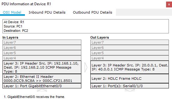
Notice the inbound and outbound PDU IP details. The inbound IP packet is encapsulated into a new IP packet because of GRE. Note the IPs used in packet headers.
That’s all the basics things you need to know about GRE tunneling. If you have any concerns, leave a comment below. I’ll reply as soon as possible.


There are certainly a couple more details to take into consideration, but thank you for sharing this information.
Thanks for the auspicious writeup. It in fact was a amusement account it. Look complicated to more introduced agreeable from you! However, how can we keep in touch?
I own read your article. It’s truly helpful. We may benefit lots from it all. Fluent writing style and even ivid thoughts make people readers enjoy reading. I could share ones own opinions along with my good friends.